ZJA 12 Transformer Oil Treatment Plant
Transformer oil treatment plant ZJA12 is used for maintenance of large power transformers. It can effectively remove the free water, gases and other solid particles from mineral transformer oils as well as natural and synthetic esters and improve its dielectric strength.
Our company is a designing, engineering and manufacturing company capable of application customization for best solutions in oil filtration, water and gas filtration, and other reclamation products
- Patent degassing and moisture removal technology
- While removing impurities, the original properties of the pressure-swing oil are retained
- Other additives and functions in the oil are not damaged
- Both stationary and mobile type are available
- Suitable to treat all type of transformer oils
Introduction of ZJA 12 Transformer Oil Treatment Plant
ZJA12 Double Stage High Vacuum Transformer Oil Treatment Plant is used to decrease total water content ( ppm) and gasses present in transformer oil. Highly efficient dual stage vacuum system with vacuum chamber housing highly effective coalescer system is an ideal solution for dehydration and gas removal. Water content is decreased to less than 5 ppm according to the IEC 60814 or ASTM D1533 standards. Total gas content is reduced down to less than 0.25% according to the IEC 60567 or ASTM D2945 standard. Particulate matter is lowered to less than 99% of particles over 1.0 microns. Dielectric breakdown is improved above 70 kV. With the use of a regeneration module acidity and interfacial tension are also improved to acceptable values by the IEC 60422 standard.
TEST DESCRIPTION | METHOD | UNIT | INITIAL OIL CONDITION | FINAL OIL QUALITY |
MOISTURE | IEC 60814 or ASTM D1533 | PPM | <100 | <5 |
BREAKDOWN VOLT | ASTM D-877 | kV | <30 | >70 |
GAS CONTENT | IEC 60567 or ASTM D2945 | % v/v | 12 | 0.25 |
PARTICLE | MICRON | <0.5 |
Features of the Transformer Oil Treatment Plant
- Vacuum system capable of generating a 1 milliliter vacuum in the vacuum chamber.
- Low watt density heaters are provided (max 1.7 watt/cm2 heating capacity) with indirect heating to prevent local overheating.
- A flow control switch that will shut down the handling machine in the event of a flow break, with the option of bypassing the switch.
- High oil level switch which will shut down the machine in case of high oil level or over-whipping in the vacuum chamber.
- The manual, electrical, hydraulic, and all actuators are installed near the machine operating panel.
- Possibility of online moisture measurement sensors on inlet and integrated into SCADA.
- Possibility of filling of the transformer.
- Possibility of Volt Meter installed.
- Possibility of Ampere Meter installed.
- Optional of full automatic control by PLC and touch screen.
- Optional of oil flow meter on outlet and display the current and accumulated flow on touch screen.
Flow Diagram
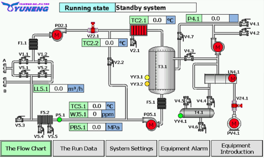
Untreated Oil Equipment→ Oil Inlet/Outlet A→ Exchange Valve, Oil Inlet Valve V1.1→Inlet Strainer F1.1→Inlet Pump PO2.1→ Solenoid Valve VZ2.1 →Heater R2.1 →Vacuum Separation Chamber T3.1→(two ways):
→Vapor →Vacuum Booster Roots Pump LC4.1 or Switch Valve V4.3→ Condenser LN4.1→Vacuum Pump PV4.1→Air ;
→Clean Oil →1st Level Atomizer WH3.1→1st Level Separating Tower ZF3.1→2nd Level Atomizer WH3.2→2nd Level Separating Tower ZF3.2→Discharge Pump PO5.1→Check Valve VL5.1→Fine Filter F5.1 àInterchange Valve, Oil outlet Valve V5.2→Oil Inlet/Outlet B→ Pending Oil Expenses Equipment
Parameter of Transformer Oil Treatment Machine
| Item | Parameter | Model / Unit | ZJA1.8 | ZJA3 | ZJA6 | ZJA9 | ZJA12 | ZJA18 | |
| Technical Parameter | Flow rate | L/H | 1800 | 3000 | 6000 | 9000 | 12000 | 18000 | |
| Working vacuity | Pa | ≤80 | |||||||
| Working pressure | Mpa | ≤0.35 | |||||||
| Temperature range | oC | 45-65 | |||||||
| Power supply | 50Hz 380V 3-Phase 4-Wire (or as requested) | ||||||||
| Total power | kw | 16 | 36 | 70 | 100 | 150 | 200 | ||
| Inlet/outlet diameter | DN | 20/20 | 25/25 | 32/32 | 40/40 | 50/50 | 65/65 | ||
| Length | cm | 160 | 180 | 220 | 250 | 280 | 345 | ||
| Size | Width | cm | 125 | 145 | 160 | 195 | 215 | 260 | |
| Height | cm | 200 | 220 | 245 | 270 | 300 | 300 | ||
| Weight | kg | 650 | 900 | 1200 | 1600 | 2200 | 3000 | ||
| Oil Treatment Index | Breakdown voltage | kV | ≥70 (Spherical electrodes) | ||||||
| Water content | ppm | ≤5 | |||||||
| Gas content | % | ≤0.3 | |||||||
| Filtering accuracy | micron | 1 | |||||||
*The machine size, the weight will change slightly due to different configurations.
Advantages of Transformer Oil Treatment Machine
Our transformer oil treatment system has been fully tested under the supervision of engineers in accordance with the specifications; the customer has obtained the transformer oil filtration system under fully feasible conditions. All components have sufficient strength and rigidity to withstand the normal conditions of transportation and use, and there are no sharp edges and corners to avoid injury to the operator under normal use conditions. The machine is designed to easily replace defective components. In addition, there are the following advantages:
- Reduce machine maintenance costs.
- Reach NAS-6.
- PPM reaches 5 PPM, bdv reaches 70 KV.
- Improve oil quality.
- Extend oil life.
- Provide constant efficiency continuous filtration/separation of transformer oil.
- Reduce oil costs in terms of consumption and inventory.
Why We Need the Transformer oil treatment plant ZJA12
Introduction of Transformer oil
Transformer oil is used in power equipment where it provides cooling and insulation protection. Over time aggregated, the water, gas content and solid particles can seriously affect these properties. Transformer oil maintenance is the key to transformer reliability, performance and longevity. Your transformer’s insulating oil should be free from moisture, dissolved gases and particles that accumulate as the oil ages. Even some new oils may require treatment to limit these contents to acceptable levels.
Technical Description of Oil Treatment Plant
– Dehydration to less than 5 ppm moisture content after several passes
– Degassing to less than 0.25% gas content by volume
– Increasing of breakdown voltage of insulating oils to 70kV
– Drying of electrical equipment while purifying the oil ( optional)
– Initial filling of electrical equipment with the insulating oils
– Evacuation of transformers and other electrical equipment
The Plant is able to filtrate oil with nominal filtration fineness up to 1 micron with solid contaminant content in accordance with Class 9 industrial purify (-/15/12 by ISO 4406).
Product Images

INLET STRAINER
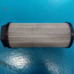
Gross particle removal-porosity 80 mesh
INLET PUMP ( Optional)
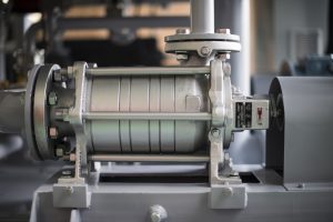
Positive displacement inlet pump with mechanical seal. The pump has rated at 10% higher flow than discharge pump. Inlet line have manual ball valve and normal close solenoid valve with manual switch be installed.
HEATER
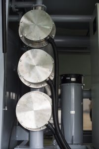
Heaters can be divided into multiple groups. Low watt density heaters are provided (max 1.7 watt/cm2 heating capacity) with indirect heating to prevent local overheating. The setting of heater is controlled by digital type temperature controller, from 20 deg C to 80 deg C. The best performance of the temperature is from 45 deg C to 65 deg C.
VACUUM CHAMBER
Vacuum chamber is the vessel for oil processing. The chamber is designed to avoid foaming. Foam detector and vacuum break valve are installed and activated all the time to eliminate the foaming problem. High and low level detectors are also installed in the Vacuum Chamber. Interior of the vacuum chamber is epoxy painting with no chemical reactivation with transformer oil. The leak rate for the vacuum chamber is less than 400 micron per hour.
VACUUM BOOSTER ROOTS PUMP
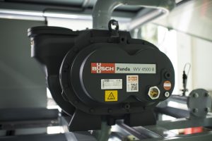
Mechanical booster, direct drive.
VACUUM PUMP
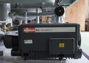
High efficiency air-cooled rotary vane pump with oil exhaust filter.
DISCHARGE PUMP
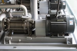
TEFC motor drive discharge pump.
FINE FILTER
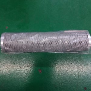
Porosity 0.5 micron.
FLOW METER
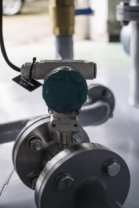
A digital type flow meter to monitor the oil flow rate and the accumulated oil process. Oil flow rate can be displayed on touch screen.
ON-LINE MOISTURE MONITORING SYSTEM ( Optional)
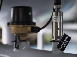
To measure moisture-in-oil in ppm. Real time moisture value is displayed on touch screen and also record not less than 5 minutes.
PLC CONTROL ( Optional)
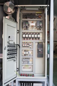
The operation of the oil treatment plant are incorporated into the complete plant and controlled by PLC and Touch Screen. The operator will interface with the oil treatment plant through the touch screen and PLC system. Vacuum Values, Heating Temperature, Flow Rate, Moisture in Oil are to be recorded by PLC and displayed on touch screen.
TOUCH SCREEN ( Optional)
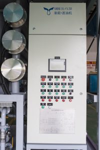
Industrial grade Window based Human Machine Interface touch screen unit is installed on the control panel to monitor and control all the process of the plant. Multi-language includes English and Chinese are support. Operator is allowed to toggles between English and Chinese display menu.


